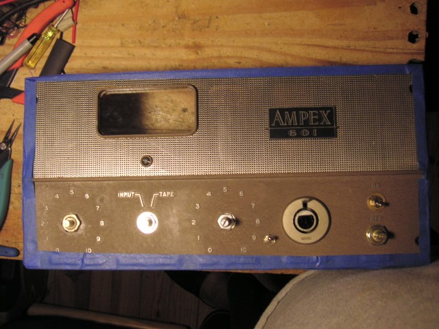
The LAmpex
This unit combines the microphone preamp section of the Ampex 601 with an LA2A limiter circuit. The LA2A design includes the UTC HA100X and UTC A-24 transformers.
There are additional options, but when they are turned off the LAmpex is close to the original.
(more details)
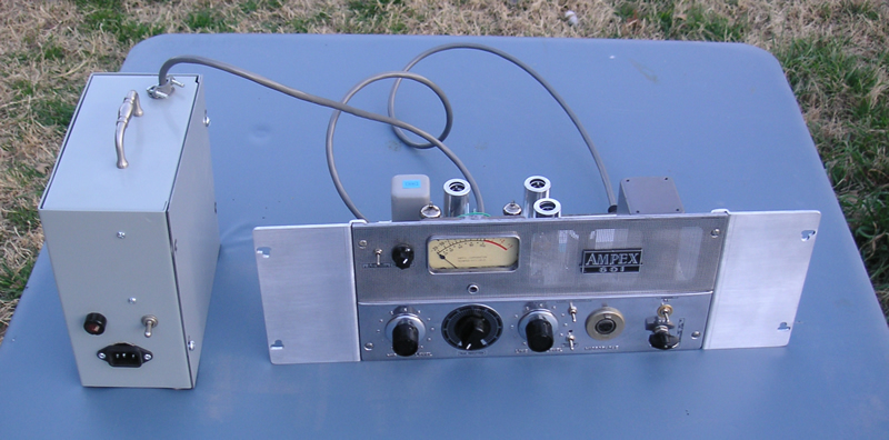
The Mic preamp utilizes EF86 and 12AY7 tubes. The Mic preamp also benefits from the fine HA100X input transformer.
When the mic preamp is turned off, the unit serves as an LA2A "clone" line level compressor/limiter.
For more information on the LA2A, this is a good place to start: Universal Audio
Sample recordings
Acoustic guitar recorded through a Studio Projects C-1 mic .
No EQ, effects, or processing except for a touch of reverb. The LAmpex was showing about 5 to 10 dB of peak reduction on the meter and was set to "limit" mode.
This unit represents my building style as of 2012. I am constantly looking to improve my units and my latest upgrades include using Mogami top quality shielded wire where it is called for, adding a copper ground buss to lower noise by improved internal grounding, Silver/teflon hook up wire for the audio paths, and using isolated ground wires for circuit and tube heater grounds. There are too many minor things to mention.
Example files:
Here are a couple recordings of a little jam. Each instrument was recorded thru this LAmpex. The "dry" file has no effects or processing of any kind - dry and raw. When I announce changes in the settings, those changes are being made to each track. No, you would probably not do this for musical reasons, but I am trying to demonstrate the different sounds of the unit. I also bring instruments (esp the bass) in and out so you can really hear into the mix for the sound of the different tracks - again, not really musical, but that isn't the point. Please keep in mind that I had only a few hours of time for this over a couple days. It isn't right to keep customers waiting while I play with their unit.
http://artist.fixthatmix.com/JDs_LAmpex-jam-dry.mp3
In the wet version, I've edited it down to just music and applied some basic FX: reverb, EQ, limiter and a little pitch correction.
http://artist.fixthatmix.com/JDs_LAmpex-jam-wet.mp3
If you really want to hear the detail, here are lossless 24 bit files of the above:
http://artist.fixthatmix.com/JDs_LAmpex-jam-dry24.flac
http://artist.fixthatmix.com/JDs_LAmpex-jam-wet24.flac
details:
Larrivee LV-09 acoustic guitar, 1940's Conn "Naked Lady" tenor sax, 1940's King 2B trombone, Gemeinhardt flute, talking drum, bongo cajon, G&L electric bass. Mic was a studio Projects C-1 (one of the early ones) No pads were used, even though it might have helped prevent me from overdriving the input in some places. (notably some of the voice)
The bass was plugged into a radio shack matching transformer and fed into the mic input. The mic preamp was engaged.
The sax, trombone, and percussion were recorded with the mic preamp disengaged. The LA2A works well like this with hot condensers and loud sources.
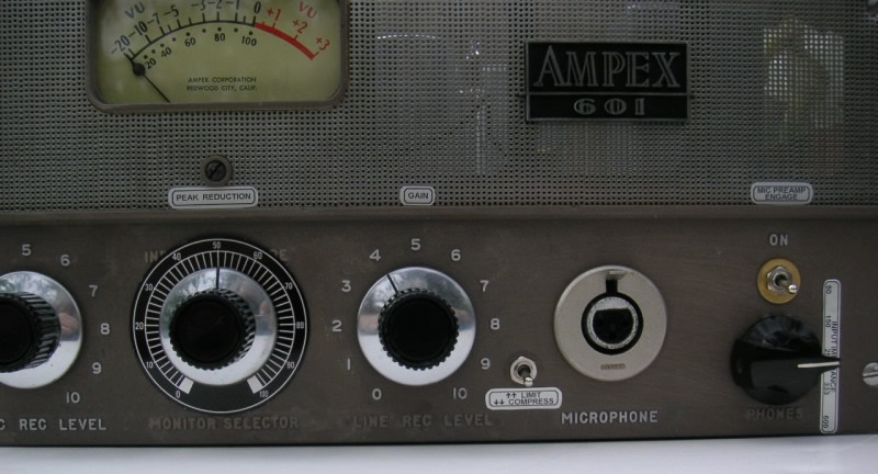
Setting up your LAmpex:
This guide is to help you get started with some basic settings. The 1st situation is for use with a microphone and the mic preamp.
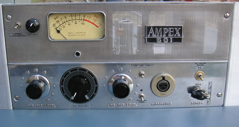
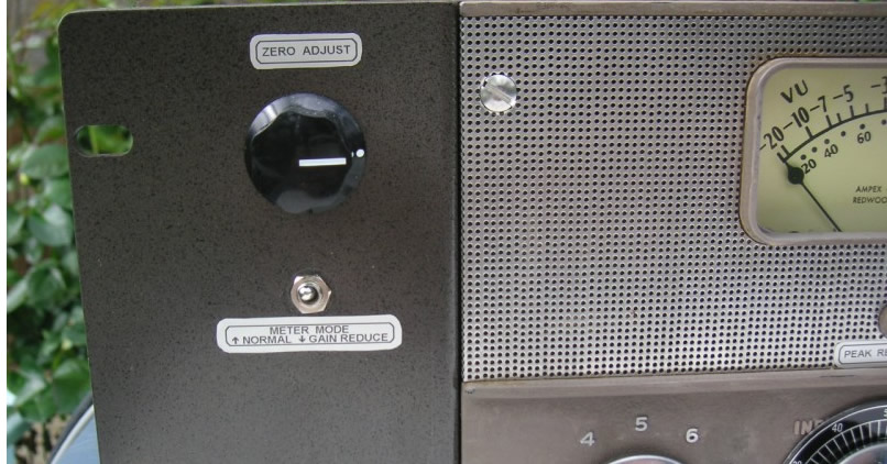
1. Place the meter switch in the "normal" position (up.)
2. Turn the mic level, peak reduce, and master gain controls to 0.
(skip down)
3. Put the limit/compress switch in the "compress" position. (not really important)
4. Select the appropriate input impedance. For most dynamic or LDC microphones, this will be the 150 or 250 Ohm position.
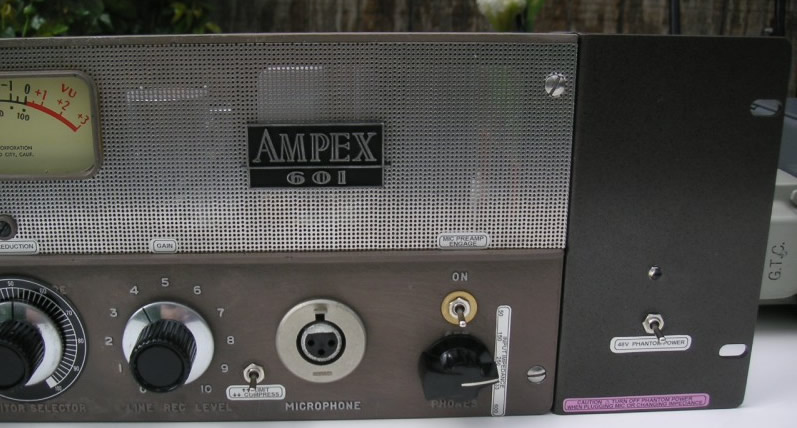
5. Turn the "Mic preamp engage" switch to the "On" position.
6. Plug the LAmpex into your system, and plug your microphone into the front.
7. Turn on phantom power if you are using a mic that requires it. Don't turn on the phantom power unless you need it.
8. Bring up the gain control to about 4.
9. Bring up the mic level control until you are getting a good signal with the meter reading about 0 on the louder peaks.
This is now set up as a mic preamp only. It is assumed that the user has a good understanding of gain staging.
Different microphones and different systems will require different settings. To avoid distortion, keep the gain a bit on the high side
and the mic level on the low side. To get some saturation, do the opposite.
Note: For loud sources and hot microphones, one can turn off the Mic Preamp Engage switch and feed the LA2A section directly. This works well for drums, horns and miked guitar amps when using LDC's.
To add compression:
1. Flip the meter into peak reduction mode.
2. Use the zero adjust control to adjust the meter until it reads 0. (you may set it for +2 or so, for more range from the meter)
3. Bring the peak reduction control up until the meter pulls to the left on louder sounds. This indicates the amount of gain reduction happening.
This is a good place to start. As you add compression, you can turn up the gain to make up for the peak reduction.
To drive the compressor harder, you may turn up the mic level. The wide variety of possible settings provides many different flavors.
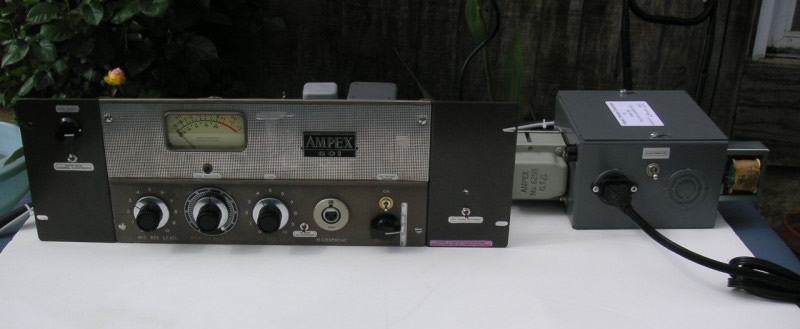
For use as an LA2A only:
Be sure the phantom power is off. NEVER turn on phantom power when the LAmpex is fed by any device other than a microphone!!
1. Turn off the Mic Preamp Engage switch.
2. The input impedance will usually be set to 600 Ohms for line input.
3. Use the unit as described above, except the mic level control is not active when the unit is used as an LA2A only.
Driving the compressor harder means turning up the output of whatever is feeding the LAmpex.
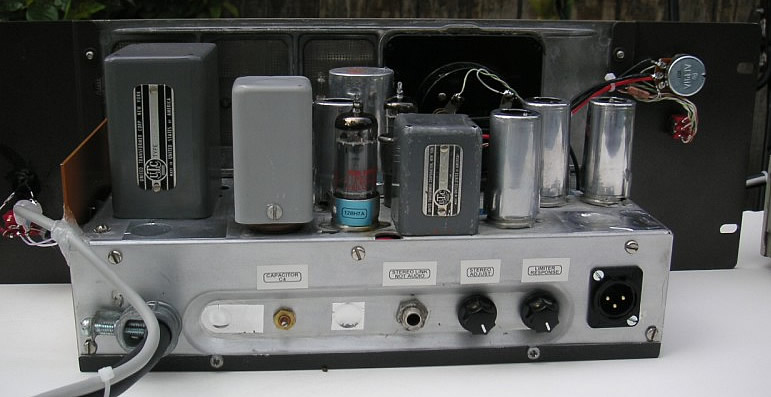
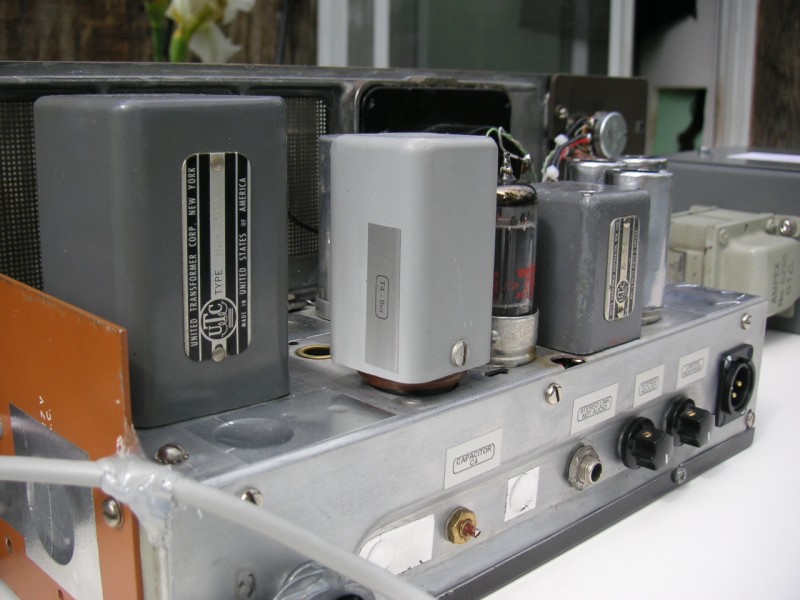
Rear controls:
These controls are rarely used. They are mostly for calibrating the LA2A section with another LA2A for use as a stereo pair.
This is a major hassle and almost no one does it.
From left to right:
1. Capacitor C4 (as labeled on the schematic) - This capacitor adjusts the way different frequencies are sent into the gain circuit as negative feedback.
Loosening this cap by turning it clockwise (yes it seems backwards) lowers the capacitance. This removes some of the bass frequencies
from the negative feedback, which has the effect of increasing the bass response of the LAmpex. Many people who clone the LA2A use a fixed value here.
These variable caps are hard to find. I have set this cap for the value which is recommended for those using a fixed cap in this place.
If the user wishes to adjust this cap, I recommend opening the unit and adjusting it from the back to avoid stripping the tiny slotted head you see above.
These caps are tight and difficult to adjust.
2. Stereo link jack - This jack is for the connecting cable used when trying to sync 2 LA2A for stereo use. It is not intended as an audio out.
3. Stereo Adjust - Used for syncing 2 LA2A. See the LA2A user manual for details.
The normal position for this control is about 90 - 100% clockwise.
4. Limiter response - This control affects the electroluminescent panel and is intended for syncing 2 LA2A. It is normally left in the fully counterclockwise position.
See the manual for details.
5. Main output
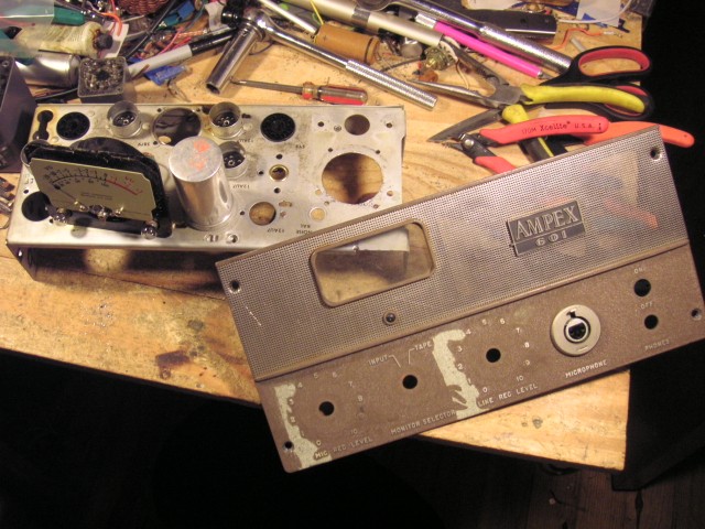
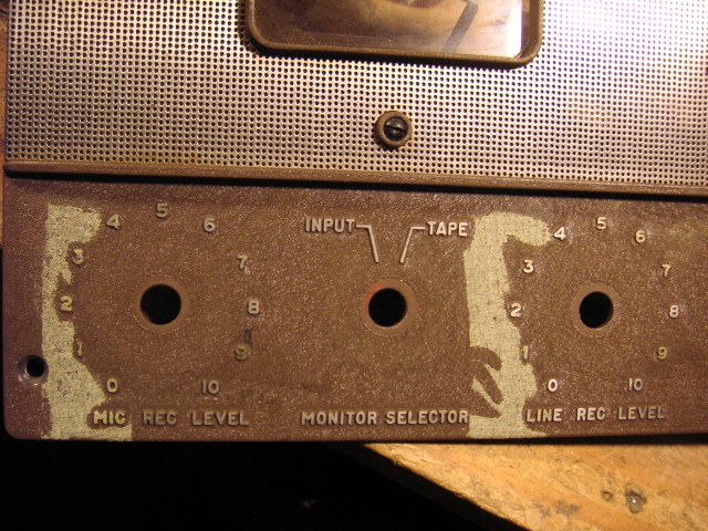
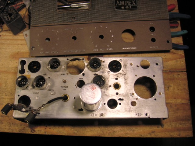
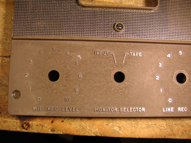
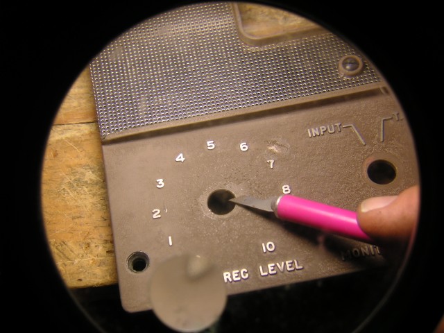
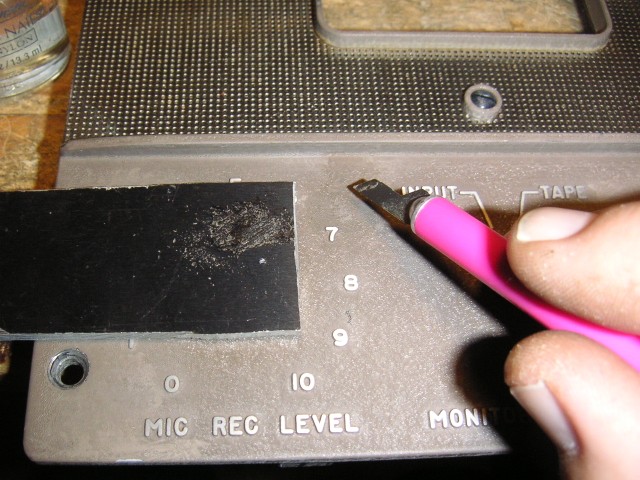
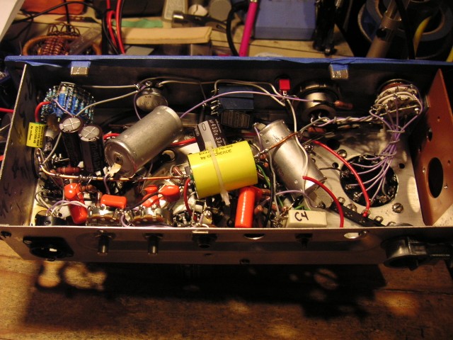
Some misc. photos from the build:
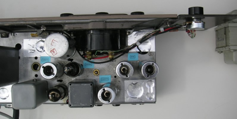
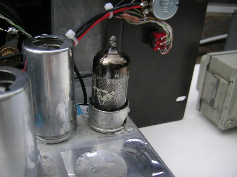
Note the punched holes in the chassis for the HA100x and A-24 transformers.
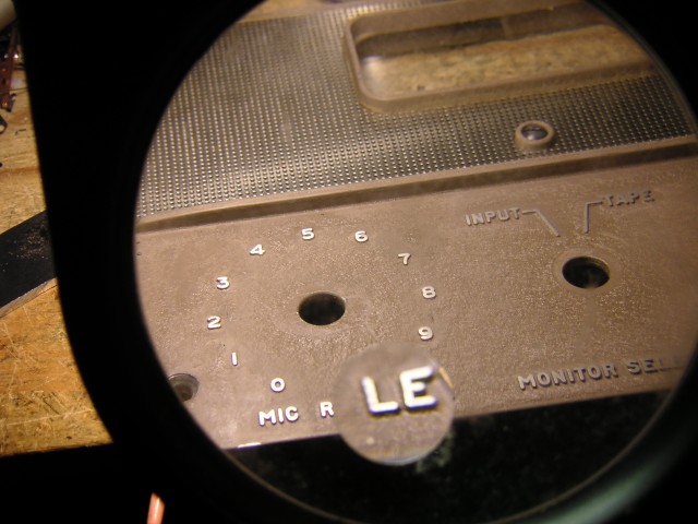
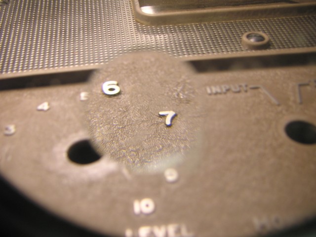
This shows a spot (next to No. 7) where the black anodized layer (primer) was missing underneath and the paint came off when cleaning:
Here I am scraping some paint from around the pot hole, to be mixed with clear nail polish to patch the bad spot.
Fixed:
Sometimes the holes in the faceplate are too big for modern components. Here I am making a special spacer to make a tight fit in the hole. (That's the Alps pot)
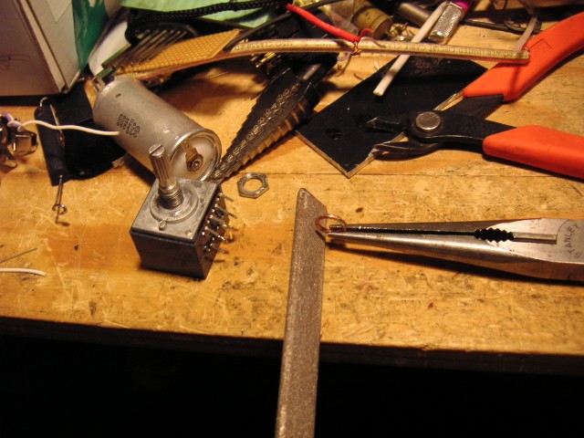

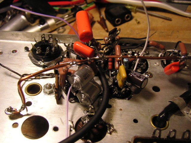
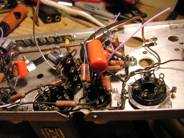
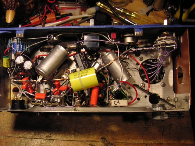
The big silver cylinders are the Russian teflon caps, the yellow ones are the Auricaps. On the left is the stepped attenuator, and on the right is the 5 way impedance switch.
My goal in this design was not to copy exactly the LA2A. As long as it is very close in sound and quality, I am satisfied.
The main differences between the LAmpex and a regular LA2A or a re-issue:
1) The T4 module is different but works in a similar fashion as the original. It uses the same photo-cells but a different EL panel.
2) This unit has a mic preamp which can be turned off for using the unit as a standard LA2A.
3) I use modern components including Auricaps in my design. I don't use the layout or turret board of the LA2A. There is simply not room in the 601 chassis, so I used plain old point-to-point wiring.
4) The meter switch has only 2 positions: GR (gain reduce) and +4. The original also had a +10 output setting for the meter. This only affected the meter and does not affect the output level. (except that it would make you tend to push the unit to a hotter level because the meter reads lower.)
5) The original used terminal strips for the I/O connections. This is flexible but a hassle. My modern design uses a 5 position impedance switch.