![]()
Setting modesty aside, this is a great tube mic preamp. From wide-open-sky air around your acoustic tracks to a warm crunchiness or all the way to a NASTY overdrive for electric guitars, this preamp shines!
|
I am not wealthy. I can't afford many different preamps. I wanted a tube preamp that could:
|
 |
I designed this to be something I'd love to use in my studio. During the prototyping work, I decided upon a feature that deserves special mention: the dual outputs. The differences between the outputs create a nice stereo sound. Of course, after recording, one has lots of mixing options. You can choose to use either one or both of the outputs later on when mixing. I consider the Altec 15095 transformer output to be the higher quality of the two. For more, see the transformers section below. |

Feature List
The feature list of this preamp is long. I will try to provide a mix of technical and plain English descriptions. Ok, enough blah-blah. Here's the quick and dirty feature list. For endless detail about these features, read below.
An ABSURD amount of detail follows:
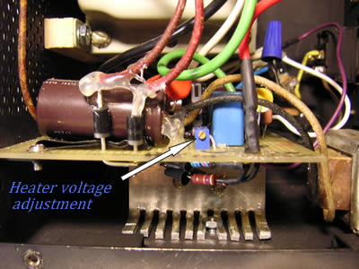
Power Supply - There are very good reasons for using tube power supplies with power amplifiers. I have never heard a good reason for using tube power supplies with preamps, however. This power supply is custom designed for this preamp. It uses parts from the original power supply, but I've chosen to replace the rectifier tube with diodes. Many people pull tubes out of the 601s to stop oscillation and cut noise, but they don't realize that they are changing the voltages supplied to the remaining tubes. I often see 601's where the heater voltage is over 8V because the unused tubes were pulled. This shortens tube life dramatically and increases noise. This power supply is designed to provide the proper voltages to the modified circuit. The heater voltage is regulated and adjustable, set at 6.28 VDC. The normal experimental range most people play with on heater voltages is 6.1 - 6.3 V. The B+ voltage is unregulated, but highly filtered and load balanced for the circuit to provide the voltages specified on the original Ampex schematic. To keep costs down, I use old computer power supply boxes. I spend the money on oversized/over-rated components and excellent 600V water/chemical resistant electric cable to carry the power to the preamp. I tend to favor function over form.
Only qualified persons should attempt adjusting the heater voltage. There are lethal voltages inside the power supply. I've provided insulation on some of the high voltage components near the heater adjustment pot, but care must be exercised and the use of a plastic screwdriver is recommended.
Power up sequence:
1) Turn power switch on the 601 to OFF, if necessary. This is a "standby" switch which turns off the (B+) high voltage to the tubes.
2) Turn switch on power supply to ON.
3) Wait approximately 10 - 15 seconds to allow the heaters to warm up.
4) Then turn the switch on the 601 preamp to ON. This turns on the high voltage to the tubes.
With solid state power supplies for tube circuits, this may help protect the tubes. This is not really important for preamp tubes like it is for power amp tubes. Will forgetting this a few times hurt? No. Some people say it is unnecessary. It is a habit to preserve the life and performance of the tubes over the long term. It was also convenient because the power supply and the 601 both had power switches. Following the recommended procedure prevents the high voltage from spiking up to about 400VDC across the entire B+ circuit. This slightly exceeds the rated voltages for some of the components for the few seconds that it occurs, so I think it is a good idea to follow this procedure even if there is no damage to the tubes from ignoring it. This issue is under some debate in tech circles.
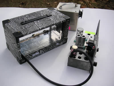
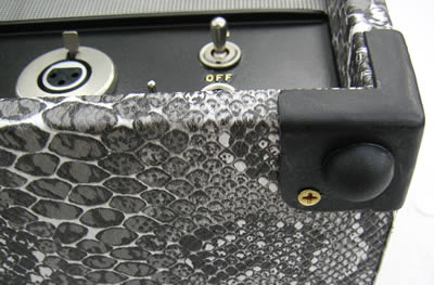
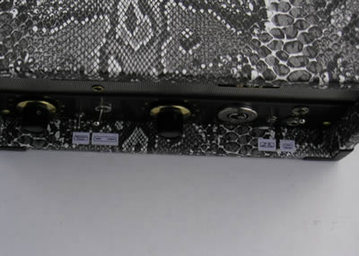
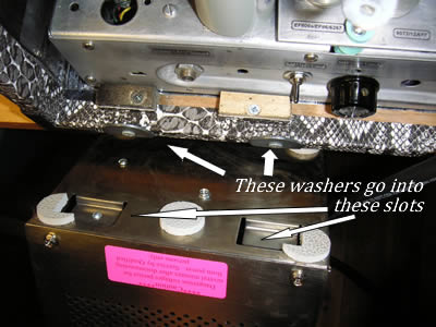
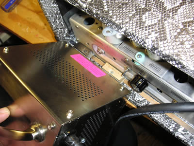
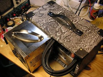
For transporting the unit, the power supply mounts solidly to the preamp:
Phantom Power (48VDC) - Phantom power circuits for use in preamps with input transformers must be particularly well implemented. The phantom resistors have been hand matched to better than .1% tolerance to prevent damage to the transformer. I also double check the resistors after soldering, to be sure the values haven't changed.
Most phantom power circuits leave at least a pair of resistor's across pins 2 and 3 of the mic jack, even when they are turned off. To preserve the original circuit's input design, I designed the phantom power to completely disconnect from the circuit when switched off - no resistors left across the input.
I STRONGLY recommend the following procedures when using phantom power:
1) Never connect or disconnect a microphone with the phantom power turned on.
2)
Leave phantom power off unless you are using it.
3) Never use a mic cable which is shorted or crackling.
If one follows the standard best practices for using phantom power, as I listed above, there is no problem. If one insists on constantly plugging and unplugging mics with the phantom power turned on, or using faulty cables, it may lead to a magnetized input transformer core over time. This will lower the sound quality and raise the noise level of the transformer.
Tube upgrades - The Ampex 600 and some 601s used the 5879 pentode tube. Later 601s were updated to the EF86/6267 tube. These tubes are not interchangeable. I build incorporating the EF86 circuitry and wiring. The EF806s is a direct substitute for the EF86, as the 6072 is a direct substitute for the 12AY7. These upgrades represent a significant noise reduction and frequency response improvement.
15 dB Microphone Pad - Many mic pads leave a resistor across the input when they are switched off. This is harmless when one is using ~200 Ohm impedance mics which include everything from the classic dynamic mics to modern condenser mics, BUT - that resistor can mess with you if you are trying to use a 30 - 50 Ohm ribbon mic. The Ampex 601 is chosen by many for use with ribbon mics, so I designed the mic pad to be completely removed from the circuit when switched off. The same idea applies to the design of the phantom power, so when both of these features are switched off, the input structure is the same as an unmodified Ampex 601. No "harmless" resistors are left in the circuit.
The mic pad is essential for using modern high output condenser mics with the Ampex 601. The mic level control does nothing to prevent the input transformer or the EF806s from being overdriven by such a hot mic with a loud source. The input signal goes to the trafo and the EF806s before it goes to the mic level control, so the hot signal from the mic overdrives the input regardless of the mic level setting. The mic pad is placed before the input transformer to remedy this situation. The distortion produced by overdriving the input is unpleasant and should be avoided. It is not the warm kind, more like static or transistor clipping.
My sax sounded terrible through the unpadded 601 with a LDC mic, even with the mic's 10 dB pad turned on. I use 1% Dale Vishay metal film resistors for the signal path resistors in the pad. They are some of the best available, renowned for being quiet, and are almost certainly superior to the resistors used in the built in pads on most condenser mics. Of course, between the typical 10 dB pad on a mic and the 15 dB pad on the preamp, there are lots of options.
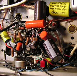
The circuit - The modifications I've made to the original circuit are to lower noise and to improve frequency response, detail and clarity; as well as providing additional features. Most of the components have been replaced, but the spirit of the circuit is preserved. I checked and kept the nice German made carbon film resistors which were used in important spots. The original signal path went through 4 gain stages and a cathode follower. The 4th stage has limited headroom and was only needed for tape playback. It has been removed. Here is the 9er-ized Ampex 601 signal path:
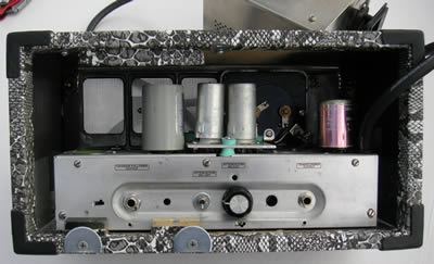
Bypassed Filter Caps - It is almost standard procedure these days to bypass the large filter caps with a much smaller value cap. I use orange drops for this purpose. The idea here is to provide a path to ground for the higher frequency harmonics of the noise. The large filter caps have a higher impedance at high frequencies that allows some of the high frequency noise to remain in the signal, instead of being passed to ground. Not only do I use special low impedance caps for the large filter caps, but I also bypass them with the small value orange drops.
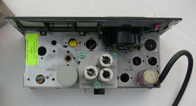
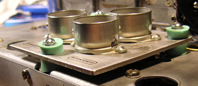
Silicone mounted tube platform - I chose to use a superb soft silicone to make the mount for the tube platform. The other choice was Sorbothane, but I have some doubts as to the long term reliability of Sorbothane for such an important duty. For rubber feet, I think its a good choice, but not for the tube platform. The heat might be an issue with Sorbothane, too. The photo below left shows the components on the underside of the platform. They are mostly free to move with the platform. This floating platform with components was inspired by the higher end Ampex preamp designs which utilize the same principles.
Transformers
Input transformers - A vintage Ampex branded transformer with gold pins is included in this auction. There are many types of transformers (trafos) which are compatible with the wiring and octal socket. There are also very many types with different wiring requirements, like the famous Altec 4722. The layout of this 601 makes it easy to rewire the sockets for experimenting or to change the impedance for ribbon mics. One 601 manual calls for the Peerless 4797 trafo, but I don't know if the earlier models with the 5879 tubes used something different. I have tried many different input trafos which have been sold for the Ampex 601 and 351 (yes, they can use the same trafos:) several different Ampex branded ones, Altec peerless, Wahlgren, and UTC. They all have slightly different sound and frequency response characteristics, but they all worked well and sound great. I have found that the Ampex branded ones with the gold pins have the best Freq response. The peerless 4797 gives a couple dB lower gain than the others, too - not that it matters - gain is not an issue with these preamps.
Output Transformers - I was stuck. I couldn't decide whether to leave the original cathode follower circuit or change it to a transformer only output. You see, the cathode follower circuit has characteristics that give the 601 its sound. For those that want that sound, it is absolutely essential, but I personally would never choose such a colored device for general purpose recording.
It occurred to me that if I found a way to incorporate both, it might give a beautiful stereo output. I did, and it does. Using both outputs as a stereo pair when recording means that later, you can decide if you want the cathode follower sound, the Altec 15095 transformer output sound, both blended to mono for panning, or kept as the original stereo. This preamp is all about versatility. I did not try to match the output levels of the two outputs. To do so would have required additional components in the signal path and I did not think it was worth it for the small difference between the outputs.
Line / Instrument Input - Mostly to preserve the look and function of the original controls, I chose to use the line level control as a way to allow both line level and instrument level (guitar) inputs. With the line level pot at 8 - 10, the line input is suitable for electric guitar and bass. To feed a standard line level like a CD player into the preamp, the line level pot should be set around 2 or 3. The output of this pot feeds the input to the 1st gain stage, then it goes to the mic level pot before it hits the 2nd gain stage. So in principle, the line level pot drives the mic level pot in a similar fashion to channel and master volume controls on a guitar amp. This allows one to dial in just the right amount of drive for warming tracks, like when using the preamp as an effect loop on a mixer channel. For more extreme tube distortion, one uses the output attenuation.
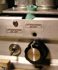 |
Output Attenuation - The attenuation is between the 3rd gain stage and the cathode follower/15095 transformer outputs. This means that you'll be driving the tubes into saturation, not the output transformers. Well, at least with normal settings within the meter's range. In extreme overdrive, with the meter defeated - all bets are off. Everything is likely to be saturated and distorting. I am not certain if this much overdriving is harmful over the long term. I recommend keeping the settings within the meter's range. For me, this represents the useful range of settings, but I wanted to leave the option for full blown insane overdrive for the more adventurous souls. Why use a switch and a pot? The switch allows the isolation of the pot when the preamp is used in normal mode, so there is no effect to the circuit until you switch it into overdrive mode. This means that if the pot is accidentally bumped or turned, it doesn't hurt anything. The switch also allows the use of a pot which is less sensitive to adjust. |
In my design work, I try to limit the number of components through which the audio signal passes. This is a case in point. The audio signal passes through no additional components to achieve attenuation. The "Attenuation On/Off " switch brings the Attenuation pot into the circuit, but not into the signal path. The attenuation changes the interstage impedances and thus, the freq response, however. (minor low end roll-off) This is shown in the freq response graphs on my site. I experimented with many options including a couple vintage Daven attenuators and settled on this solution. It performs every bit as well as the Davens.
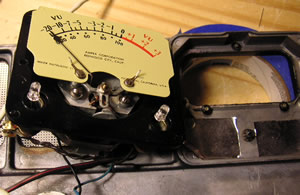 |
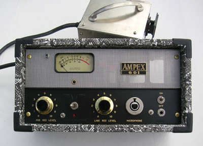
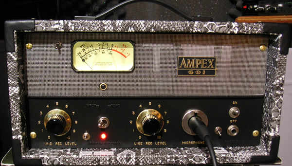
The meters in the 601 are very delicate and risky to disassemble. The paint of the meter background likes to separate from the metal plate and flake off. In most cases, the meter must be disassembled to replace the light bulbs. To prevent the owner from dealing with the delicate task of replacing the meter lights and possibly damaging the meter, I have replaced the light bulbs with white LED's which should last a very long time. During this process, I check the paint for separation and seal down any loose paint with clear acrylic sealer. Most meters need some touch ups and I don't guarantee that they are perfect or like new. |
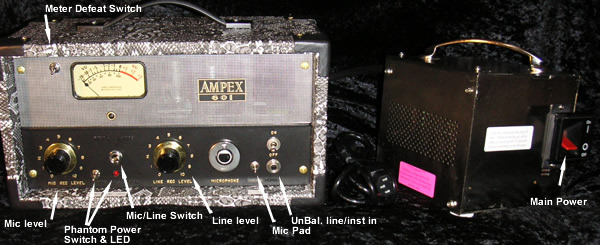
The Meter - The meter reflects the output level of the cathode follower output. 0 VU corresponds to ~1.3 volts at the output, or about +4dBm. When fed into my audio card (set to +4dB input) pegging the meter corresponds to digital clipping at the sound card and going into the red indicates mild tube warmth (in normal mode,) so it's just right. There is also a "Meter Defeat" switch to protect the meter when driving the tubes and output transformers to extreme. This switch can also be useful when recording quiet, exposed tracks because the meter adds distortion (.3% THD according to specs) and mechanical noise which is picked up by microphonic tubes. I have heard this with an EF86 on an unmodded 601. One can hear the meter needle hit the peg. I have not heard this noise with the EF806s tube and silicone mounted platform.
Specs - These specs are the result of using a PC based analysis program.
IMD - .3%.
The THD was reported as ~.5% typical across most of the spectrum as well as the standard 1000Hz.
(This was at -3 dB on the VU meter. As one gets to 0 VU and above, the distortion starts climbing as is normal and desirable in a tube preamp.)
For frequency response charts, please see my main ampex 601 page.
Typical self noise has been reduced almost 20 dB compared to an unmodified 601. Similar improvements are seen in the signal to noise ratio.
I have over $550 invested in the parts and materials in this unit. This is 9er-ized Ampex 601 unit #001. It is not the prototype, but it is the first of this series of Ampex 601's I've produced for sale. The prototype is much uglier ;-)