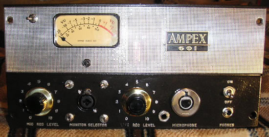
AMPEX 601 Dual Mono Altec
(Note: This is a very old page and much of it is obsolete)
This design offers 2 matched preamp channels. Each has the full original circuit path of the 601 and my favorite mod: the addition of an Altec 15095 output transformer tapped off after the microphone preamp section of the 601.
The tape electronics section has been converted to a second mic/line preamp channel. Old carbon composition resistors have been replaced with Dale/Vishay 1% metal film resistors on both channels so they will match for use as a stereo unit.
In the past, I have tried to use some of the old caps to try to preserve more of the "vintage sound." Even desirable caps reported to last (Budroc, Bumble bees, and ceramic caps) are failing these days and finding caps originally spec'd at 5% tolerance which are 100% or more out of spec has lead me to start replacing all the important components with high quality modern components. For those that are looking for that "vintage sound," please consider: when these units were fairly new, these components would not have been so out of spec. What you get with a deteriorated vintage unit is not the same performance that was achieved when they were new. To me, what is most important about the "vintage sound" comes from the tubes, the tube circuitry, and the transformers (The Iron!) Supporting those components with high quality caps and resistors provides excellent performance.
Front panel features:
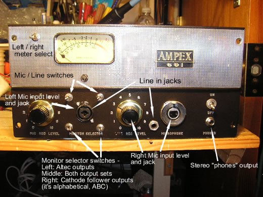
1) L/R meter switch - One of the things I really dislike is when companies try to hide the drawbacks to their product through misdirection and misleading ads. I will tell you straight out about the things that are not ideal about a design. In this design, the metering isn't great. With 4 outputs (L/R Altec and L/R CF) and only one meter, one has to accept that the metering is limited. I felt it was very important to be able to check levels for all the outputs, so I designed the metering options to allow for this. There is a rotary switch on the back which selects the output to be metered. Then one can flip the meter switch on the front between L and R. According to specs, the meter adds up to .3% THD. Some may wish to turn off the meter after setting levels. Honestly, I can't hear any extra distortion, but it is measurable.
2) Mic / Line switches (the upper 2 switches of the 4 shown below) - Individual switches means that one may use the mic input on one channel and the line input on the other. Flip the switches to the left for Mic and to the right for Line. (the left switch is for the left channel, etc.)
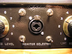
3) Monitor selector switches (the lower 2 shown above) - These switches select the output for each channel. In the left position, the Altec output is active. In the right position, the cathode follower output is active. There is also a middle position which makes both outputs active. So we have (A)ltec, (B)oth and (C)athode follower; from left to right. I chose to try to make the design logical enough so I would not have to slap labels all over it.
There are some strange things that can happen with certain combinations of these switches, what the outputs are feeding, and the termination switches on the back. Nothing harmful, but you will have some loss of gain from the extra loading of the circuits. Rule of thumb: When using both outputs, turn off the termination for the Altec outputs for best results. In fact, I prefer the sound of the Altecs when unterminated in most situations.
4) Line inputs - (unbal. 1/4" TS 250k impedance) The new channel uses a Neutrik combo jack for both the XLR and line inputs. I had to add a jack for the original channel. These inputs are suitable for electric guitars as well as line level outputs from a CD player for example. These preamps work beautifully as the front end for a listening system. I listen to music played on a CD player and run into the line inputs, with the outputs of the preamp feeding my power amps and speakers - nothing else in the signal chain. The sound is very good. If I were prone to hype my designs, I would say "amazing."
5) Stereo "phones" output - I use the quotes around phones because this output does not have the oomph to power modern low Z headphones above a very low volume. I intended this to be a usable headphone output, but it really isn't. (The original "phones" output was mono.) What it is really good for, is as a Hi-Z output to feed a mixer, sound card, or similar device. This is an important feature for those that like different colors because these outputs do not go through an output transformer and they have a slightly different sound. The best use of this output is with a standard effect loop insert cable such as is used on some mixers (shown below.) Of course any splitter that provides 2 outputs from a 1/4" TRS plug can be used. (I don't recommend using a TS cable in this output jack, only TRS.)

Rear Panel Features: 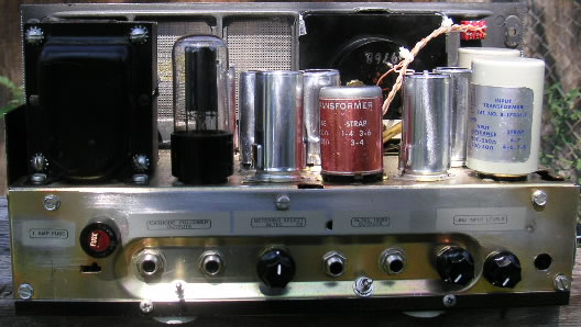
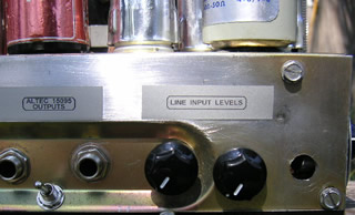
1) Outputs - These outputs are 1/4" TRS balanced outputs. (Unbalanced TS cables can be used here for unbalanced output, also.) On the left, we have the cathode follower outputs. The Altec outputs are on the right.
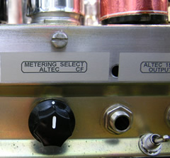
2) Metering select switch - This switch has more than the 2 positions which are marked (Altec and CF.) The other positions are meter defeat. (no connection)
3) Termination switches - These are the switches located between the output jacks. Up is 600 Ohm termination on, down is off. These switches allow one to turn off the termination which is usually desired when feeding modern gear with a vintage 600 Ohm output. When feeding modern gear, the termination allows for proper frequency response from the circuit. However, there may be times when a different flavor is desired or even more gain, so I have found that there are no rules when it comes to whether you use the termination or not. (well, ... actually one strong suggestion: When using both sets of outputs at the same time, I recommend turning off the termination on the Altec outputs.)
4) Line input levels - These are the L and R line-in level controls.
Side panel features:
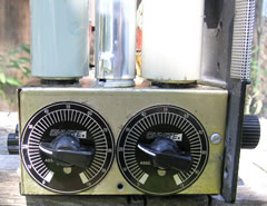
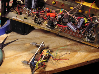
I have replaced the original screw adjusted "rec cal pots" with these nice new pots, knobs and faceplates. These controls serve as master level controls for the cathode follower outputs. One uses these to control the amount of "tubeyness," color, or distortion - take your pick. If one turns these controls down and turns up the input levels, more color is the result. Everything from a filthy, nasty grunge to a very clear sound is possible. These controls only work with the cathode follower outputs. The Altec outputs provide the cleanest sound and simplest signal path, but don't have the overdrive capability of the cathode follower sections.
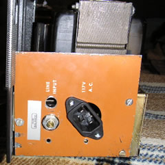
The AC power section has been moved as far to this end and away from the audio circuits as possible. The Hum balance control has been relocated here and the fuse as well in order to keep wires short and away from audio wiring. (The fuse is on the rear.)
Additional Info and pictures
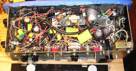
This is the most densely packed unit I have done to date. Getting all the components in for 2 full channels was a challenge. It required the construction of a special platform for the cathode follower transformers (shown below.) I don't prize neatness for its own sake. I prefer short wires to neatly routed ones. I also prefer to use direct connection of components and minimize the use of jumper wires. These things give the appearance of a rat's nest, but any tech who looks close will find important wires crossing at right angles and the construction done in layers where the audio wiring layer is as removed from the noisy layer as possible.