|
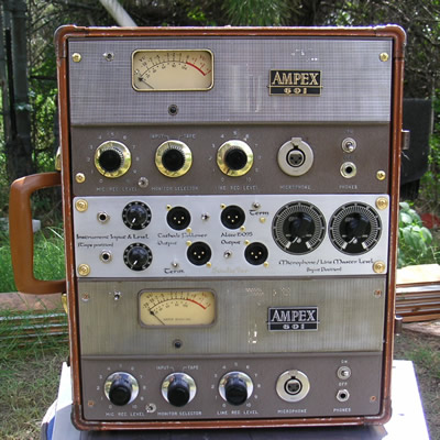
Ampex 601 Mini-Mod This unit offers a lot of versatility. There are so many ways to use these units that it can become a bit confusing. I will try to lay out the various options and features as clearly as I can. With this set of mods, I tried to maintain as much as possible of the original circuitry/components, while still replacing the components which are known to deteriorate over time. Some components are replaced so the units will be more symmetrical.
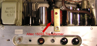
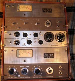
Features: 1) Converted Tape Input: The tape input section has been converted to an instrument input. There is a rotary switch which allows the user to select either the 6F5 triode, the EF86 pentode, or both for heavier distortion effects, as the front end for the instrument input. 2) Altec 15095 output: The new output utilizes a vintage Altec 15095 to provide a balanced line output from the mic preamp section of the 601. This mod provides an excellent quality circuit for general purpose recording, whereas the full original circuit has more color.
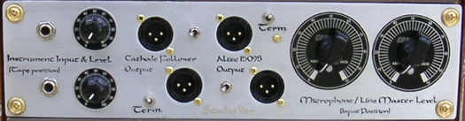
3) "Term" switches allow one to turn off the termination which is usually desired when feeding modern gear with a vintage 600 Ohm output. When feeding modern gear, the termination allows for proper frequency response from the circuit. However, there may be times when a different flavor is desired or even more gain, so I have found that there are no rules when it comes to whether you use the termination or not. The upper Term switch terminates both the upper XLR outputs and the lower terminates the lower ones. The upper half of the controls goes with the upper unit and the lower half belongs to the lower unit. (the left master mic control goes with the upper unit)
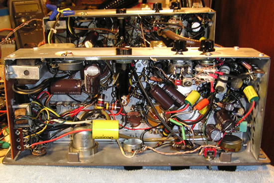
4) Output Select Switches (located between the output XLR jacks) allow selection of the full original circuit path including the reproduce amplifier section, a new output featuring the Altec 15095 transformer, or both. The middle position on the output select switch selects both outputs. There is some loading down of the circuit when using both outputs, but this setup can be fun with instruments since the 2 outputs have different sound and timing because of the differences between the circuits. 5) Usable level controls: The Microphone/Line Master Level controls replace the "Rec Cal" pots seen on the original schematic. Likewise, the Instrument Level controls replace the Playback Level pots (P.B. Level.) The XLR output jacks are gold pin Neutriks. 6) Recap: Electrolytic and paper capacitors have been replaced with some of the highest quality caps around. For electrolytics, I use Nichicon PW series caps and for the coupling caps I prefer using Auricaps - perhaps the finest and most transparent caps available. The original "Budroc Cornells" and the ceramic caps are not known to deteriorate and were not replaced. There's a spot where I replace an electrolytic with an Auricap polypropylene cap. When these units were made, they really had little choice but to use an electrolytic for the 4 µF cathode follower output cap. It's all that was available at a reasonable cost.
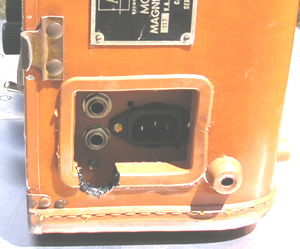
7) Line inputs & Mic/Line switch: (1/4" TS) Line inputs for both units are next to the power jack. The one on top goes with the top unit. The line input has been modified from the original circuit to provide more gain and to be separated from the microphone input. The original circuit mixed the 2 inputs which causes minor noise and other problems. Separating the 2 inputs and setting the interstage impedance for the second tube to a fixed value is an important upgrade IMHO.
8) Meter switches: The switch beside the meter allows one to monitor the level of either the original cathode follower output or the Altec 15095 output. The middle position is: meter off. The simple way to remember how to set the meter switch is to make it the same as the output select switch. 9) Impedance selector switches: These gold contact switches are specially purchased for this one job of allowing the user to select 30 - 50 Ohm impedance for ribbon mics, or 150 - 250 Ohm for dynamics and condensers. When the switch is up: 150 - 250 Ohms. When down: 30 - 50 Ohms. (Up is high, down is low)
10) Upper unit access: The rivets holding the top cover plate were drilled out and replaced with screws for easy access to the upper unit's tubes.
Here is a block diagram for one unit to help understand the signal paths. Please notice that one can use the upper path through the 15095 output and the lower path through the original output, at the same time - 2 separate signal paths:
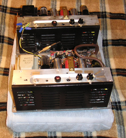
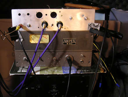
Cobbled together for early testing:
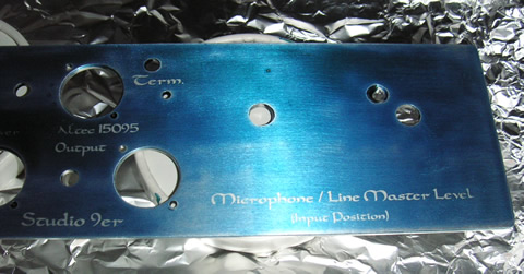
Making the faceplate:
|
More Ampex 600 series info: Most of the Ampex 600 and 601 tape decks/preamps (with the mic transformer) work pretty well with dynamic mics like the classic shure sm-58 and also vintage ribbon mics. In fact, I have never heard a 58 sound as good as it does through the 9er-ized 601. Unmodified 601s still use the 4th amp stage which limits (IMHO) the 601 for general purpose recording. It does provide overdrive capability and is a worthwhile circuit. This stage adds a pot/voltage divider(can be used as an attenuator for overdriving) to lower the signal followed by an amplification stage to bring it back up then the cathode follower. This colors the sound and is less transparent than the Altec 15095 (or other transformer) tapped off after the mic preamp section. If you Google for Ampex 601 you'll see people talking about using it for a special effect - distorted vocal or bass guitar preamp. You'll also find mention of how noisy they are. They can be noisy, but they can also be fairly quiet when they are setup well. The 601 tape decks were only rated at 40 - 15k frequency response. The preamps are a diamond in the rough however, since their circuitry is based on classic tube preamp design incorporating a pentode first stage, followed by a dual triode. In the 601, it has been compromised by size and cost restrictions, as well as the compromises due to the tape electronics. These are some of the reasons the unmodified 350 / 351 sells for 4 times as much as the 601. The 601 is a great candidate for mods and upgrades, though. The belt driven decks like the 601 aren't prized for their mechanical performance, so converting them isn't too frowned upon. |
||||||||||||||
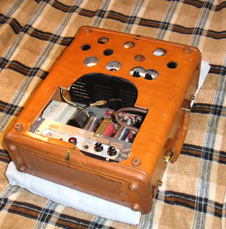
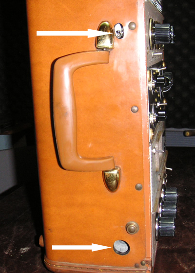
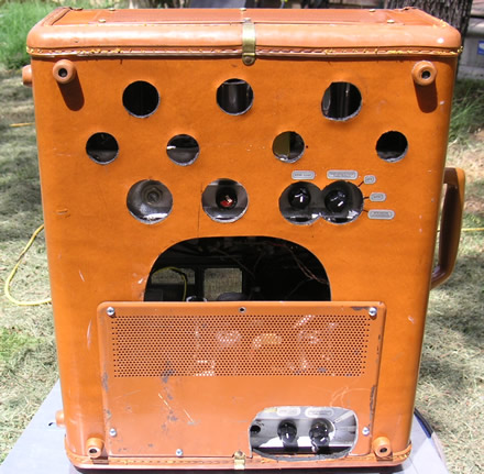
Disassembly To gain access to the units for service or mods, one needs to remove the 12 screws holding all 3 sections in place. The top 2 screws have nuts on the back. One must remove the top cover plate and reach in with a finger to hold the nut for removal.
Then roll the whole thing over onto its face ...
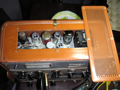
... and gently lift the back off being careful not to catch on the impedance switches.
|
 These Mini-mod units are to be used as mic/instrument/line preamps. I disconnect or reuse some of the tape related circuits, so these aren't intended for use with the mechanics of the 601.
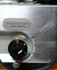
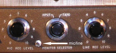 Set the mic/line switch to the left for mic; right for line.
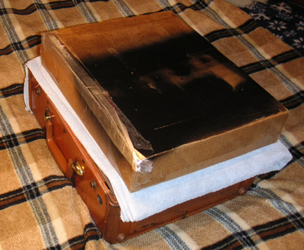
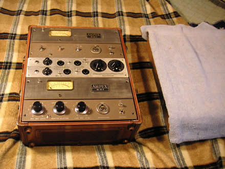 After the fasteners are removed, place a folded towel or other pad over the face of the unit. Then place a support on the pad. A piece of plywood, or in this case, a sturdy box works well.